
|
|
|
|
||||||
 |
COMPUTER AIDED DESIGN | |||||
| Once
a solid foundation has been provided in terms of accurate base maps, the
architectural format of your system can be analyzed with confidence. The final design will reflect the predetermined major trunk routing and design specifications set forth by your company. The design will provide the most economical layout possible with special consideration given to long term maintainability of the system. Every effort will be made to place amplifiers and power supplies street-side. Power supply inserters will be placed at amplifier inputs or at splitter locations. Amplifier information required for routine system maintenance will be located adjacent to the amplifier or in an info block in a sectional box format. The design Bill Of Materials (BOM) will indicate the exact quantities of materials required to complete your system. Williams Communications, Inc. utilizes state of the art computer workstations and the latest versions of CAD and HFC design software. Below are our current design platforms: AutoCAD Map Series Software, Lode Data, OSP InSight, ESRI / Arc View, Microstation Bentley Comms, Map Info |
||||||
| CAD
SERVICES
- Land Base, Strand Maps, System As-builts, Digitizing
Old As-builts, MDU Details, Permit Drawings, Profile Maps, Database Development |
||||||
| GEOSPATIAL LAND BASE - Creation from electronic city/county/ maps, USGS maps, or State grid maps. |
||||||
STRAND DIGITIZING – Maps are digitized to a customer specified scale with all pole information or Underground information digitized on the maps. |
||||||
| AS-BUILT DIGITIZING – System as-builts will be digitized to a customer specified scale with all system information and field notes digitized on maps. | ||||||
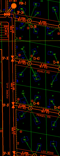
| COAXIAL SYSTEM DESIGN – Design, powering and Bill Of Materials (BOM) by phase or node. All design will be digitized to a customer specified scale. New, Rebuild, Retrofit, Upgrades, Distortion Analysis, Trunk gain Analysis, Design Specifications, BOM’s | ||||||
| FIBER
OPTIC DESIGN
– FTTx, node layout, routing, splice documentation, headend engineering
and Bill of Materials provided by node or phase. All fiber design will
be digitized to a customer specified scale. |
||||||
|
||||||